
 [contact-form-7 id=”3145″ title=”Contact form 1″]


The post Tesla Powerwall appeared first on Gold Coast Solar Power Solutions.
[contact-form-7 id=”3145″ title=”Contact form 1″]
The post Tesla Powerwall appeared first on Gold Coast Solar Power Solutions.
You may have heard of solar power battery storage before, but why has it become such a hot topic recently?
The main reason can be found in the following graph.
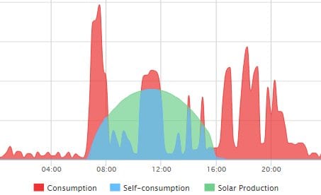
The green area in the graph shows solar power which is generated by the solar power system but hasn’t been required; it’s called surplus power. We buy power at around 25c a kWh so the blue section of the graph is saving 25c a kWh but the green surplus power is being sent back to the grid, usually for only around 6 to 8c a kWh. At that low rate it doesn’t make sense to send surplus power back to the grid, so why not store it in batteries and draw from it when you need it?
For 2016 it looks like it’s the new catch cry of solar power sales people, yes I can assure you that this solar power system is battery ready! But buyer beware, as the term battery ready is a very loose and open ended term, as okay you may one day be able to connect a battery bank to your solar power system but just how much work and additional components will that require? Will it just be a matter of buying a compatible battery bank to connect into the system or will thousands and thousands of additional dollars be required to actually get the battery bank to work with your system?
You see the issue here is that in both cases a solar power system can be called “battery ready” by a sales person but the difference is in how much extra work and components are required to actually get the solar power system working in conjunction with a battery.
Solar panels – this ones pretty obvious, for a solar power system to be what it is you need solar panels!
 Hybrid Solar Inverter – for a solar power system to work with batteries you need a hybrid solar inverter – it’s called a hybrid as it’s a standard grid connect inverter but it can also charge and discharge batteries, hence the hybrid name. For 3 phase supplies we recommend the Fronius SYMO hybrid inverter, for single phase systems we recommend the SolarEdge StorEdge solar inverter.
DC Coupled Battery Storage Solar Power Systems
Both these solar inverters are designed to be “DC coupled” to a battery bank such as the Tesla PowerWall; this is the most efficient way to connect a battery bank as the system is designed to take the DC solar power generated by the solar panels and send it onto the batteries as DC power.
AC Coupled Battery Storage Solar Power Systems
Most other solar inverters out there which can connect to battery banks and may be classed as battery ready use what’s called an “AC coupled” system to take the power from your solar panels to the battery. This is quite inefficient as the DC power from the solar panels is converted by the inverter into AC power, then back to DC power to charge the batteries. When the power stored in the batteries is required it is then once again converted from DC to AC for use. Each of these conversions from DC to AC and AC to DC lowers the efficiency of the system which is why it’s not recommended as the best option for a solar power system with battery storage.
A great new device from SMA called the Sunny Boy Storage is an AC coupled system which is separate to your grid connect inverter and can couple to any existing grid connect inverter system to store your surplus power. This product is designed to work with the Tesla PowerWall Home Battery which Gold Coast Solar Power Solutions are certified installers of.
Electricity Meter – this is not your standard meter that your power company reads but a separate electricity meter which communicates with your battery control system to tell  the batteries what to do. It constantly monitors the power consumption of your property and this important data is used to tell the hybrid inverter what to do with the power from the batteries and from the solar panels. If the solar power system is producing more power than your property is consuming it will automatically send the required solar power to be used to power your appliances and send the surplus power to charge the batteries. If the property starts using more power than the solar is providing it will draw the additional power as required from the batteries. Obviously this electricity meter is a crucial component to maximise the self consumption of your solar power; if you are wanting your solar power system to be battery ready we highly recommend installing the electricity meter to suit the battery storage system initially, as the data that this meter provides will help you select the optimum sized battery when you are ready to look at them.
A point that needs raising in regards to battery ready solar power systems is what happens if there’s a blackout and you lose power from the grid? If your intending to put in a battery storage system you’re probably just expecting power will be available from your batteries if the grid goes down – right? Well BEWARE! – this is not necessarily the case!
The battery storage systems such as the SolarEdge StorEdge inverter, Fronius Hybrid, do provide backup power of some essential loads, but beware that quite often this is not the case! It’s worth asking the question as you don’t want to find out when there’s a blackout and you were expecting to have power.
As we have discussed many standard grid connect solar power systems can be called “battery ready” however if you ever wanted to upgrade the system to actually work with batteries you would be looking at potentially more than $5000 in additional costs to get the system ready to work with batteries; and that cost is before the cost of batteries.
At Gold Coast Solar Power Solutions we highly recommend if you want to install a solar power system that is truly “battery ready” to initially install an inverter system which can be DC coupled to the batteries such as the 3 phase Fronius SYMO hybrid inverter system or the Single phase SolarEdge StorEdge solar inverter. This will be the most efficient system which is ready for any future technological advances – DC coupled systems are the future without a doubt. We also highly recommend installing an electricity meter with the initial installation as it will provide valuable data on your power requirements and will be invaluable in sizing the optimal battery storage to go with your solar power system – a system that is truly battery ready!

Got A Question About Solar Power? Click Here For Answers!
The post Solar Power Battery Storage appeared first on Gold Coast Solar Power Solutions.
A little while Gold Coast Solar Power Solutions was asked to provide a solar power proposal for a local Gold Coast childcare center which of course we were very happy to do. After submitting our proposal we did not hear from them for a couple of months so we gave them a call. The manager proceeded to tell me that they had signed up with another company for a much larger system than we had proposed. Let’s just look at this situation and the savings this childcare center can expect.
Firstly some background on the current state of solar power feed-in tariffs in QLD. You may or may not be aware that the current QLD solar power net feed-in tariff pays 8c per kWh for any surplus solar; this is the power that the solar power system has produced but has not been used on the property at that moment so it has been sent back to the power grid as surplus electricity to be used next door or where ever it is required. The electricity account holder currently gets paid the feed-in tariff rate of 8c per kWh of surplus power, plus any further incentive that their electricity retailer offers such as those offered by Click Energy.
What you are probably not aware of is some of the finer details of this feed-in tariff which can be found on the website here, mainly as follows:

The graph above shows the childcare centres power consumption from midnight to midnight on a weekday, a perfect example of a power load suited for a solar power system to cover, averaging around 6 kW during the day.

The graph above shows the childcare centres power consumption from midnight to midnight on a weekend. As the facility is only used on weekdays this is just stand by loads and fridges etc. The average load here is around 1 kW, both day and night.
From this data, it is clear to see that a solar power system producing much more than 6 kW of power would be producing a fair amount of surplus solar power to the business’s requirements, and this additional solar power production would be going back to the grid as surplus power at little to no benefit to the business, remembering from the information above that a system with an inverter larger than 5 kW will not be receiving the 8c state feed-in tariff, therefore the maximum they could receive for this surplus power would be 8c per kWh from the electricity retailer AGL; Click Energy pay 10c per kWh but they have their feed-in tariff capped at a 5 kW system as well.
Taking all this information into account we provided a solar power proposal specifying 30 x quality REC 250W solar panels (7.5kW in total) coupled with an SMA Sunnyboy 5000TL inverter for the following reasons (a side note half the panels were to face NE and half NW):
On following up this business about our solar power quotation I was told by the manager that they had gone with another company with a 15 kW system and that they would be selling all the surplus power on the feed in tariff. My alarm bells where ringing!! Let’s look at the immediate issues:
The post Solar Power Example: Incorrectly Sized System appeared first on Gold Coast Solar Power Solutions.

The Delta RPI Home Series range of solar inverters can develop a number of different faults, when a fault is present an error message will be displayed on the screen. Below is a list of error messages, explanations on the error or fault and a list of actions to take to resolve the issue.
If you have one of the error or fault messages below we recommend you follow the listed actions to take to remove the fault before contacting a company who can help you further such as Gold Coast Solar Power Solutions.

| Message | Possible Cause | Action |
|---|---|---|
| AC Freq High |
1. Actual utility frequency is over the OFR setting 2. Incorrect country setting 3. Detection circuit malfunction |
1. Check the utility frequency on the inverter terminal 2. Check country setting 3. Check the detection circuit inside the inverter |
| AC Freq Low |
1. Actual utility frequency is under the UFR setting 2. Incorrect country or Grid setting 3. Detection circuit malfunction |
1. Check the utility frequency on the inverter terminal 2. Check country & Grid setting 3. Check the detection circuit inside the inverter |
| Grid Quality | Non-linear load in Grid and near to inverter |
Grid connection of inverter need to be far away fromnon-linear load if necessary |
| HW Connect Fail |
1. Wrong connection in AC plug 2. Detection circuit malfunction |
1. Check the AC connection, must accords to manual 2. Check the detection circuit inside the inverter |
| No Grid | 1. AC breaker is OFF 2. Disconnect in AC plug |
1. Switch on AC breaker 2. Check the connection in AC plug and make sure it connects to inverter |
| AC Volt Low | 1. Actual utility voltage is under the UVR setting 2. Incorrect country or Grid setting 3. Wrong connections in AC plug 4. One or more internal fuses are broken 5. Detection circuit malfunction |
1. Check the utility voltage connection to the inverter terminal 2. Check country & Grid setting 3. Check the connection in AC plug 4. Replace fuses (FUC1-3) and check all switching devices in boost & inverter stages 5. Check the detection circuit inside the inverter |
| AC Volt High | 1. Actual utility voltage is over the OVR setting 2. Utility voltage is over the Slow OVR setting during operation 3. Incorrect country or Grid setting 4. Detection circuit malfunction |
1. Check the utility voltage on the inverter terminal 2. Check the utility voltage on the inverter terminal 3. Check country & Grid setting 4. Check the detection circuit inside the inverter |
| Solar1 High | 1. Actual Solar1 voltage is over 1000Vdc 2. Detection circuit malfunction |
1. Modify the solar array setting, and make the Voc less than 1000Vdc 2. Check the detection circuit inside the inverter |
| Solar2 High | 1. Actual Solar2 voltage is over 1000Vdc 2. Detection circuit malfunction |
1. Modify the solar array setting, and make the Voc less than 1000Vdc 2. Check the detection circuit inside the inverter |
| Insulation | 1. PV array insulation fault 2. Large PV array capacitance between Plus to Ground or Minus to Ground or both. 3. Detection circuit malfunction |
1. Check the insulation of Solar inputs 2. Check the capacitance, dry PV panel if necessary 3. Check the detection circuit inside the inverter |
| Solar1 Low | 1. Actual Solar1 voltage is under the limit 2. Some devices were damaged inside the inverter if the actual Solar1 voltage is close to “0” 3. Detection circuit malfunction |
1. Check the Solar1 voltage connection to the inverter terminal 2. Check all switching devices in boost1 3. Check the detection circuit inside the inverter |
| Solar2 Low | 1. Actual Solar2 voltage is under the limit 2. Some devices were damaged inside the inverter if the actual Solar2 voltage is close to “0” 3. Detection circuit malfunction |
1. Check the Solar2 voltage connection to the inverter terminal 2. Check all switching devices in boost2 3. Check the detection circuit inside the inverter |
| HW FAN | 1. One or more fans are locked 2. One or more fans are defective 3. One ore more fans are disconnected 3. Detection circuit malfunction |
1. Remove the object that stuck in the fan(s) 2. Replace the defective fan(s) 3. Check the connections of all fans 4. Check the detection circuit inside the inverter |
| HW DC Injection |
1. Utility waveform is abnormal 2. Detection circuit malfunction |
1. Check the utility waveform. Grid connection of inverter need to be far away from non-linear load if necessary 2. Check the detection circuit inside the inverter |
| Temperature High |
1. The ambient is over 60℃ (The installation is abnormal) 2. Detection circuit malfunction |
1. Check the installation ambient and environment 2. Check the detection circuit inside the inverter |
| HW NTC1 Fail |
1. Ambient temperature >90℃ or <-30℃ 2. Detection circuit malfunction |
1. Check the installation ambient and environment 2. Check the detection circuit inside the inverter (RTM1) |
| Temperature Low |
1. Ambient temperature is <-30℃ 2. Detection circuit malfunction |
1. Check the installation ambient and environment 2. Check the detection circuit inside the inverter (RTG1) |
| HW NTC4 Fail |
1. Ambient temperature >90℃ or <-30℃ 2. Detection circuit malfunction |
1. Check the installation ambient and environment 2. Check the detection circuit inside the inverter (RTH1) |
| HW DSP ADC1 |
1. Insufficient input power 2. Auxiliary power circuitry malfunction 3. Detection circuit malfunction |
1. Check the input voltage, must > 150Vdc 2. Check the auxiliary circuitry inside the inverter 3. Check the detection circuit inside the inverter |
| HW DSP ADC2 |
1. Insufficient input power 2. Auxiliary power circuitry malfunction 3. Detection circuit malfunction |
1. Check the input voltage, must > 150Vdc 2. Check the auxiliary circuitry inside the inverter 3. Check the detection circuit inside the inverter |
| HW DSP ADC3 |
1. Insufficient input power 2. Auxiliary power circuitry malfunction 3. Detection circuit malfunction |
1. Check the input voltage, must > 150Vdc 2. Check the auxiliary circuitry inside the inverter 3. Check the detection circuit inside the inverter |
| HW Red ADC1 |
1. Insufficient input power 2. Auxiliary power circuitry malfunction 3. Detection circuit malfunction |
1. Check the input voltage, must > 150Vdc 2. Check the auxiliary circuitry inside the inverter 3. Check the detection circuit inside the inverter |
| HW Red ADC2 |
1. Insufficient input power 2. Auxiliary power circuitry malfunction 3. Detection circuit malfunction |
1. Check the input voltage, must > 150Vdc 2. Check the auxiliary circuitry inside the inverter 3. Check the detection circuit inside the inverter |
| HW Efficiency |
1. The calibration is incorrect 2. Current feedback circuit is defective |
1. Check the accuracy of current and power 2. Check the current feedback circuit inside the inverter |
| HW COMM2 | 1. Red. CPU is idling 2. The communication connection is disconnected |
1. Check reset and crystal in Red. CPU 2. Check the connection between Red. CPU and DSp |
| HW COMM1 | 1. DSP is idling 2. The communication connection is disconnected 3. The communication circuit malfunction |
1. Check reset and crystal in DSP 2. Check the connection between DSP and COMM 3. Check the communication circuit |
| Ground Current |
1. PV array insulation fault 2. Large PV array capacitance between Plus to Ground or Minus to Ground 3. Either side of boost driver or boost choke malfunction 4. Detection circuit malfunction |
1. Check the insulation of Solar inputs 2. Check the capacitance (+ <-> GND & – <-> GND), must < 2.5uF. Install a external transformer if necessary 3. Check boost driver & boost choke 4. Check the detection circuit inside the inverter |
| HW Connect Fail |
1. Power line is disconnected inside the inverter 2. Current feedback circuit is defective |
1. Check the power lines inside the inverter 2. Check the current feedback circuit inside the inverter |
| RCMU Fail | 1. RCMU is disconnected 2. Detection circuit malfunction |
1. Check the RCMU connection inside the inverter 2. Check the detection circuit inside the inverter |
| Relay Test Short |
1. One or more relays are sticking 2. The driver circuit for the relay malfunction |
1. Replace the defective relay(s) 2. Check the driver circuit inside the inverter |
| Relay Test Open |
1. One or more relays are abnormal 2. The driver circuit for the relay malfunction 3. The detection accuracy is not correct for Vgrid and Vout |
1. Replace the defective relay(s) 2. Check the driver circuit inside the inverter 3. Check the Vgrid and Vout voltage detection accuracy |
| Bus Unbalance |
1. Not totally independent or parallel between inputs 2. PV Array short to Ground 3. Driver for boost is defective or disconnected 4. Detection circuit malfunction |
1. Check the inputs connections 2. Check the PV Array insulation 3. Check the driver circuit for boost inside the inverter 4. Check the detection circuit inside the inverter |
| HW Bus OVR |
1. Driver for boost is defective 2. Voc of PV array is over 1000Vdc 3. Surge occurs during operation 4. Detection circuit malfunction |
1. Check the driver circuit for boost inside the inverter 2. Modify the solar array setting, and make the Voc less than 1000Vdc 3. N/A 4. Check the detection circuit inside the inverter |
| AC Current High |
1. Surge occurs during operation 2. Driver for inverter stage is defective 3. Switching device is defective 4. Detection circuit malfunction |
1. N/A 2. Check the driver circuit in inverter stage 3. Check all switching devices in inverter stage 4. Check the detect circuit inside the inverter |
| HW CT A Fail |
1. Test current loop is broken 2. CSC1 is defective 3. Detection circuit malfunction |
1. Check the connection of WC3 to CNC16 2. Replay CSC1 with new one 3. Check the detection circuit inside the inverter |
| HW CT B Fail |
1. Test current loop is broken 2. CSC2 is defective 3. Detection circuit malfunction |
1. Check the connection of WC3 to CNC16 2. Replace CSC2 with new one 3. Check the detection circuit inside the inverter |
| HW CT C Fail |
1. Test current loop is broken 2. CSC3 is defective 3. Detection circuit malfunction |
1. Check the connection of WC3 to CNC16 2. Replace CSC3 with new one 3. Check the detection circuit inside the inverter |
| HW AC OCR | 1. Large Grid harmonics 2. Switching device is defective 3. Detection circuit malfunction |
1. Check the utility waveform. Grid connection of inverter need to be far away from non-linear load if necessary 2. Check all switching devices in inverter stage 3. Check the detection circuit inside the inverter |
| HW ZC Fail | The detection circuit for synchronal signal malfunction |
Check the detection circuit for synchronal signal inside the inverter |
| DC Current High |
1. Switching device in boost is defective 2. Driver for boost is defective 3. Input current detection circuit malfunction |
1. Check all switching device in boost 2. Check the driver curcuit for boost inside the inverter 3. Check input current detection circuit |
| Message | Possible cause | Action |
|---|---|---|
| E01: Grid Freq Over Rating |
1. Actual utility frequency is over the OFR setting 2. Incorrect country setting 3. Detection circuit malfunction |
1. Check the utility frequency on the inverter terminal 2. Check country setting 3. Check the detection circuit inside the inverter |
| E02: Grid Freq Under Rating |
1. Actual utility frequency is under the UFR setting 2. Incorrect country or Grid setting 3. Detection circuit malfunction |
1. Check the utility frequency on the inverter terminal 2. Check country & Grid setting 3. Check the detection circuit inside the inverter |
| E07:Grid Quality |
Non-linear load in Grid and near to inverter |
Grid connection of inverter need to be far away from non-linear load if necessary |
| E09: No Grid | 1. AC breaker is OFF 2. Disconnect in AC plug 3. Internal fuses are broken |
1. Switch on AC breaker 2. Check the connection in AC plug and make sure it connects to inverter 3. Replace fuses and check all switching devices in boost & inverter stages |
| E10: Grid Volt Under Rating |
1. Actual utility voltage is under the UVR setting 2. Utility voltage is under the Slow UVR setting during operation 3. Incorrect country or Grid setting 4. Detection circuit malfunction |
1.&2. Check the utility voltage connection to the inverter terminal. 3. Check country & Grid setting |
| E11: Grid Volt Over Rating |
1. Actual utility voltage is over the OVR setting 2. Utility voltage is over the Slow OVR setting during operation 3. Incorrect country or Grid setting 4. Detection circuit malfunction |
1.&2. Check the utility voltage on the inverter terminal 3. Check country & Grid setting |
| E13: Slow Over Voltage Range |
1. Actual utility voltage is over the OVR setting 2. Incorrect country or Grid setting 3. Detection circuit malfunction |
1. Check the utility voltage on the inverter terminal 2. Check country & Grid setting 3. Check the detection circuit inside the inverter |
| E26:Slow Over Frequency Range |
1. Actual utility frequency is over the OFR setting 2. Incorrect country or grid setting 3. Detection circuit malfunction |
1. Check the utility frequency on the inverter terminal 2. Check country setting 3. Check the detection circuit inside the inverter |
| E27:Slow Under Frequency Range |
1. Actual utility frequency is under the UFR setting 2. Incorrect country or Grid setting 3. Detection circuit malfunction |
1. Check the utility frequency on the inverter terminal 2. Check country & Grid setting 3. Check the detection circuit inside the inverter |
| E28: Slow Under Voltage Range |
1. Actual utility voltage is under the UVR setting 2. Incorrect country or Grid setting 3. Detection circuit malfunction |
1. Check the utility voltage on the inverter terminal 2. Check country & Grid setting 3. Check the detection circuit inside the inverter |
| E30: DC Volt Over Rating |
1. Actual Solar1 voltage is over 550Vdc (RPI-H3) or 1000Vdc (RPI-H5) 2. Detection circuit malfunction |
1. Modify the solar array setting, and make the Voc less than 550Vdc (RPI-H3) or 1000Vdc (RPI-H5) 2. Check the detection circuit inside the inverter |
| E32: L/N Reversed |
1. Incorrect AC wiring 2. Incorrect AC connection setting |
1. Check if brown wire is connected to Line and blue wire is connected to Neutral. 2. Check display “AC configurat.” setting |
| A01: DC Offset Over Rating |
1. Utility waveform is abnormal 2. Detection circuit malfunction |
1. Check the utility waveform. Grid connection of inverter need to be far away from non-linear load if necessary 2. Check the detection circuit inside the inverter |
| A05: NTC Over Temp |
1. The ambient temp. is over 60℃ 2. Detection circuit malfunction |
1. Check the installation ambient and environment 2. Check the detection circuit inside the inverter |
| A06: Inside NTC Circuit Fail |
1. Ambient temp. >100℃ or <-24℃ 2. Detection circuit malfunction |
1. Check the installation ambient and environment 2. Check the detection circuit inside the inverter |
| A08: Heat Sink NTC1 Fail |
1. Boost heat sink temp. >100℃ or <-24℃ 2. Detection circuit malfunction |
1. Check the installation ambient and environment 2. Check the detection circuit inside the inverter. |
| A09: Heat Sink NTC2 Fail |
1. Inverter heat sink temp. >100℃ or <-24℃ 2. Detection circuit malfunction |
1. Check the installation ambient and environment 2. Check the detection circuit inside the inverter |
| A15:DSP ADC Vgrid/Iout Fail |
1. Auxiliary power circuitry malfunction 2. Detection circuit malfunction |
1. Check the auxiliary circuitry inside the inverter 2. Check the detection circuit inside the inverter |
| A16:DSP ADC Vin/Vbus Fail |
1. Auxiliary power circuitry malfunction 2. Detection circuit malfunction |
1. Check the auxiliary circuitry inside the inverter 2. Check the detection circuit inside the inverter |
| A17:DSP ADC Iin/Iboost Fail |
1. Auxiliary power circuitry malfunction 2. Detection circuit malfunction |
1. Check the auxiliary circuitry inside the inverter 2. Check the detection circuit inside the inverter |
| A18:RED. ADC Vgrid Fail |
1. Auxiliary power circuitry malfunction 2. Detection circuit malfunction |
1. Check the auxiliary circuitry inside the inverter 2. Check the detection circuit inside the inverter |
| A19:DSP ADC Iout_dc Fail |
1. Auxiliary power circuitry malfunction 2. Detection circuit malfunction |
1. Check the auxiliary circuitry inside the inverter 2. Check the detection circuit inside the inverter |
| A20: Efficiency Inconsistent |
1. The calibration is incorrect 2. Current feedback circuit is defective |
1. Check the accuracy of current and power 2. Check the current feedback circuit inside the inverter |
| A22: Internal Comm Fault_R |
1. DSP is idling 2. The communication connection is disconnected 3. The communication circuit malfunction |
1. Check reset and crystal in DSP 2. Check the connection between DSP and COMM 3. Check the communication circuit |
| A24: Residual Curr Over Rating |
1. PV array insulation fault 2. Large PV array capacitance between Plus to Ground or Minus to Ground 3. Either side of boost driver or boost choke malfunction 4. Detection circuit malfunction |
1. Check the insulation of Solar inputs 2. Check the capacitance (+ <-> GND & – <-> GND), must < 2.5uF. Install an external transformer if necessary 3. Check boost driver & boost choke 4. Check the detection circuit inside the inverter |
| A25: Ground Fault |
1. PV array insulation fault 2. Large PV array capacitance between Plus to Ground or Minus to Ground or both. 3. Detection circuit malfunction |
1. Check the insulation of Solar inputs 2. Check the capacitance, dry PV panel if necessary 3. Check the detection circuit inside the inverter |
| A27: RCMU Circuit Fail |
1. RCMU is disconnected 2. Detection circuit malfunction |
1. Check the RCMU connection inside the inverter 2. Check the detection circuit inside the inverter |
| A28: Relay Short |
1. One or more relays are sticking 2. The driver circuit for the relay malfunction |
1. Replace the defective relay(s) 2. Check the driver circuit inside the inverter |
| A29: Relay Open |
1. One or more relays are abnormal 2. The driver circuit for the relay malfunction 3. The detection accuracy is not correct for Vgrid and Vout |
1. Replace the defective relay(s) 2. Check the driver circuit inside the inverter 3. Check the Vgrid and Vout voltage detection accuracy |
| A30: Bus Unbalance |
1. Not totally independent or parallel between inputs 2. PV Array short to Ground 3. Driver for boost is defective or disconnected 4. Detection circuit malfunction |
1. Check the inputs connections 2. Check the PV Array insulation 3. Check the driver circuit for boost inside the inverter 4. Check the detection circuit inside the inverter |
| A31: Bus_P Over Volt Rating |
1. Driver for boost is defective 2. Voc of PV array is over 550Vdc (RPI-H3) or 1000Vdc (RPI-H5) 3. Surge occurs during operation 4. Detection circuit malfunction |
1. Check the driver circuit for boost inside the inverter 2. Modify the solar array setting, and make the Voc less than 550Vdc (RPI-H3) or 1000Vdc (RPI-H5) 3. N/A 4. Check the detection circuit inside the inverter |
| A33: Bus_N Over Volt Rating |
1. Driver for boost is defective 2. Voc of PV array is over 550Vdc (RPI-H3) or 1000Vdc (RPI-H5) 3. Surge occurs during operation 4. Detection circuit malfunction |
1. Check the driver circuit for boost inside the inverter 2. Modify the solar array setting, and make the Voc less than 550Vdc (RPI-H3) or 1000Vdc (RPI-H5) 3. N/A 4. Check the detection circuit inside the inverter |
| A35: Bus Volt Over Rating |
1. Driver for boost is defective 2. Voc of PV array is over 550Vdc (RPI-H3) or 1000Vdc (RPI-H5) 3. Surge occurs during operation 4. Detection circuit malfunction |
1. Check the driver circuit for boost inside the inverter 2. Modify the solar array setting, and make the Voc less than 550Vdc (RPI-H3) or 1000Vdc (RPI-H5) 3. N/A 4. Check the detection circuit inside the inverter |
| A36:Output Curr Transient Over |
1. Surge occurs during operation 2. Driver for inverter stage is defective 3. Switching device is defective 4. Detection circuit malfunction |
1. N/A 2. Check the driver circuit in inverter stage 3. Check all switching devices in inverter stage 4. Check the detect circuit inside the inverter |
| A37: AC Curr Over Rating |
Detection circuit malfunction | Check the detect circuit inside the inverter |
| A42: CT Current Sensor Fail |
1.Inverter choke Fail 2.Output Filter Fail 3. Detection circuit malfunction |
1. Check Inverter choke inductance. 2. Check output filter capacitance. 3. Check the detection circuit inside the inverter |
| A45: HW OOCP |
1. WB1 WB2 misconnection. 2. Detection circuit malfunction |
1. Check the connection of WB1 and WB2. 2. Check the detection circuit inside the inverter |
| A50:Zero Cross Circuit Fail |
The detection circuit for synchronal signal malfunction |
Check the detection circuit for synchronal signal inside the inverter |
| A56:Hardware Incompatibility |
1. HW power rating incorrect | 1. Check comm. HW power rating info. |
| A60: DC Curr Over Rating |
1. Switching device in boost is defective 2. Driver for boost is defective 3. Input current detection circuit malfunction |
1. Check all switching device in boost 2. Check the driver circuit for boost inside the inverter 3. Check input current detection circuit |
| A70: DC Curr Transient Over |
1. Switching device in boost is defective 2. Driver for boost is defective 3. Input current detection circuit malfunction |
1. Check all switching device in boost 2. Check the driver circuit for boost inside the inverter 3. Check input current detection circuit |


Got A Question About Solar Power? Click Here For Answers!

The post Delta RPI Home Series Solar Inverter faults & error codes appeared first on Gold Coast Solar Power Solutions.
Most solar power inverters come with a display to show you some basic information about what the system is doing however for more advanced monitoring and we recommend online solar power system monitoring.
While the basic display on your solar inverter is helpful for a quick check on your solar system the full system history and performance an online monitoring portal has to offer can be extremely valuable. With your solar power system connected to the internet, either by WiFi, Ethernet or via the cellular network all data from the system’s performance can be logged and stored on the inverter manufacturers monitoring portal. These monitoring portals can take this mass of data from your solar power system and present it in a visual way that can help you at a
The post Online Solar Power System Monitoring appeared first on Gold Coast Solar Power Solutions.
Solar energy has become very popular nowadays as it is a cost-effective alternative to traditional sources of electricity. If we talk about the benefits of solar panels, it is used to capture the energy from solar energy and is used in houses and establishments all over the world. Here are some advantages of solar energy and panels in this blog.
Solar panels benefits us by reducing our electricity bills. It is used in residential, commercial and other areas to reduce the need of the electric grid. With government incentives and tax readily available, this results in large cost savings.
Solar energy benefits us by generating clean energy without any damaging pollutants of greenhouse gases. This helps us to lessen our carbon footprint and aid in the fight against climate change by embracing solar energy.
Solar panels’ Low Maintenance and Long Longevity make them a Reliable and Durable Energy Source. Solar panels have a low maintenance requirement and a long lifespan. Many producers give warranties of up to 25 years and they are made to survive extreme weather.
Use of Solar Panel can also result in energy security and independence. By creating their electricity, individuals and companies can minimise their dependence on traditional sources of energy and lower the chance of power disruptions.
Solar energy is adaptable and widely available. It may power a wide range of applications, including those for homes, companies, and even transportation. Nowadays, it is more accessible than before, overall credit goes to the technological breakthroughs that have made them more effective and inexpensive.
Installation of the solar panel may raise the property value, due to this, Solar panel benefits the solar panels are in high demand by the homeowners, business owners, since they use less energy and are more environmentally friendly.
Solar energy reduces the world’s dependence on fossil fuels, which are more expensive and harmful for the environment. By using solar panels, we minimise the usage of harmful fossil fuels and move to a cleaner, and step to a more environment friendly future.
Solar energy is a clean and sustainable energy source because it doesn’t emit any damaging pollutants or greenhouse gases. We can drastically lower our carbon footprint and contribute to the fight against climate change by adopting solar energy.
Overall, solar energy and solar panels have a variety of advantages for people, companies, and society at large.
The post The Benefits & Advantages of Solar Energy & Solar Panels appeared first on Gold Coast Solar Power Solutions.
